2012-02-17 Using basic IO with .NET Microframework
Here is the code from my first French TechDays demo. The video is available here. During this first demo, I explained how to use the IO in a simple way: OutputPort, InterruptPort, InputPort and Analogic input ports. So those ports are really the basic one you can use in a .NET Microframework (NETMF) boards like the netduino one I'm using. All boards do also includes more advances IO like UART (serial), SPI, I2C and more. I'll probably do other posts to explain how to use more advance ports.
Here is the structure of the code and the global variables. I'll use this to explain each function later in this code.
using System;
using System.Net;
using System.Net.Sockets;
using System.Threading;
using Microsoft.SPOT;
using Microsoft.SPOT.Hardware;
using SecretLabs.NETMF.Hardware;
using SecretLabs.NETMF.Hardware.NetduinoPlus;
namespace ButtonBlinking {
  public class Program {
    static OutputPort LED;
    static InterruptPort IntButton;
    static InputPort Button;
    static bool IsBlinking = false;

    public static void Main()
    public static void Blinking()
    public static void LightWhenOpturated()
    static void IntButton_OnInterrupt(uint port, uint state, DateTime time)
    public static void Blink()
    public static void ButtonPressedLight()
    public static void ReadAnalogic()
  }
}
As their name are very explicit, an OutputPort is a digital IO port to do an outpout. Main functions are Write and Read. And you write or read a boolean. Write(true) will outpout a high signal (1) and write(false) will output a low signal (0).
An InputPort is also very explicit ![]() . You can read it. It can be high (true, 1) or low (false, 0).
. You can read it. It can be high (true, 1) or low (false, 0).
An InterruptPort is an input port but it can raise interruption when there is a change in the status of the the port.
Now you get the bases, lets go for more. To execute this code, you'll need couple of hardware things:
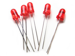
- leds (1 or 2 is quite enough)
- resistors (65 ohms)
- a press button or a switch
- a light sensor resistor or temperature sensor resistor For the main function, the code is simple, it just call the various sub function we will review in detail. So unhide the function you want to execute:
public static void Main() {
  //Demo 1: blinking a led
  //Blinking();
  //Demo 2: lighting a led when button pressed
  //ButtonPressedLight();
  //Demo 3: blinking a led when a sensor is opturated
  //LightWhenOpturated();
  //Demo 4: Analogic input
  //ReadAnalogic();
  Thread.Sleep(Timeout.Infinite);
}
So we will start with the most basic demo you can do with IO on a NETMF board like netduino: blinking a led. This this the hello world of hardware ![]()
The code is very simple:
public static void Blinking() {
  //Open an OutputPort
  LED = new OutputPort(Pins.GPIO_PIN_D0, true);
  while (true) {
    //write the opposite value read in the LED status
    LED.Write(!LED.Read());
    //wait some time
    Thread.Sleep(200);
    //effect = blinking
  }
}
You create an OutputPort one of of the digitial IO. Here the 0. And in an infinite loop, you write the opposite of the value you read on this port. And wait couple of milliseconds before doing this operation.

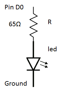
On the hardware part, all what you have to know is a simple rule: U = RxI
The output port is a 3.3V on a netduino. And reading the documentation of a led, the average voltage is 2V (vary a bit from green, red and orange) and the current it normally need to receive is 0.02A.
So applying this to calculate the needed resistor will give R = (3,3 - 2)/0,02 = 65 Ohms
Plug the resistor on pin D0 of the board, and then the led and connect it to the ground.

Run the code. And the magic happen ![]() you have a lighting led. Wow!!!! Congratulations, you've achieve level 1: blinking the led. Good! Want more? OK, you'll get more.
you have a lighting led. Wow!!!! Congratulations, you've achieve level 1: blinking the led. Good! Want more? OK, you'll get more.
Now let control the led regarding the state of a press button (or interrupter/switch).
The code is also very simple and straight forward:
public static void ButtonPressedLight() {
  LED = new OutputPort(Pins.GPIO_PIN_D0, true);
  Button = new InputPort(Pins.GPIO_PIN_D5, false, Port.ResistorMode.PullUp);
  while (true) {
    LED.Write(Button.Read());
    Thread.Sleep(10);
  }
}
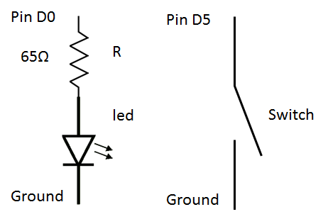
We are creating an outpout port, an input port and in an infinite loop, we aligned the state of the button with the state of the switch. On the electronic part, also very simple:

So when you will close the switch, the state of the input port will go to the ground so to 0 and it will switch off the Led. When the switch will be open, the state is high so 1 and the led will be lighted.
The next one is about the same. The idea is to blink the led 5 times when the switch is closed and 5 times when it is open again. As you can imagine, it's not easy to do in an in finite loop like previously. Plus, you will probably use your board to do something while you are waiting for the user to do an action or to get a state change on a pin. For this, there is then interrupt port. The idea is to raise an event when the state change. And as you will do with a regular .NET code, you'll handle it and do something in this event handler.
Here is the code:
public static void LightWhenOpturated() {
  LED = new OutputPort(Pins.GPIO_PIN_D0, false);
  // the pin will generate interrupt on high and low edges
  IntButton = new InterruptPort(Pins.GPIO_PIN_D12, true, Port.ResistorMode.PullUp, Port.InterruptMode.InterruptEdgeBoth);
  // add an interrupt handler to the pin
  IntButton.OnInterrupt += new NativeEventHandler(IntButton_OnInterrupt);
}
static void IntButton_OnInterrupt(uint port, uint state, DateTime time) {
  if (IsBlinking == false)
    Blink();
} public static void Blink() {
  IsBlinking = true;
  int i = 0; while (i<5) {
    LED.Write(!LED.Read());
    Thread.Sleep(200); i++;
  }
  IsBlinking = false;
}
The main "difficulty" is to declare correctly the interrupt port and the event handler. You can choose with the last parameter to generate the interruption only when you change from state low to high or high to low or both direction. Here it's bi directional so on both edges. The function IntButton_OnInterrupt will be called when the sate will change. And from there the function to blink. I've voluntarily added some "control" code to not call the blinking function when it's already in use.
On the hardware part, it's like the previous one except that I'm using here pin 12. This is because I used a more sophisticated switch. See this post.
When you will close the switch, the light will blink 5 times so if if was off, it will finish on. Now open it again, it will blink 5 times and go back to off. So what happen if you close it and open it before you light finish to blink? will the IntButton_OnInterrupt function be called right away and because of the test to see if we are blinking or not, it will stay on the on mode after blinking 5 times? Or not?
Answer is not! The interruption are serialized and it wait for the previous one to finish. So it will wait for the blink function to return to call the IntButton_OnInterrupt one. And that's the mane reason why you have as a parameter the DateTime parameter. So if you did not have time to handle an interruption and want to skip it you can do it.
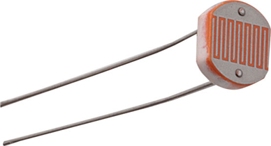
Still there? Wow, that's cool, you want some more? yes? OK, so let go for the last part: the analogic input. To illustrate this, we will need to use a temperature or light resistor. It cost couple of euros cents. They act like a resistor. The resistor vary regarding the temperature or the light.

To change a bit, let start with the hardware part. In my case I'm using a very simple light sensor acting like a resistor from 1M Ω (dark) to 100 Ω (very bright).
In order to use it and use the most of the input range (in netduino 1024 points), you need to know the average resistance which can be calculated like this: R = √(MaxR x MinR) = √(1M x 100) = 10K Ω

We will use the following simple electronic schema to measure the variance of the light sensor. Again, all what you need as an electronic knowledge is U = RxI
The analogic input Voltage = 3.3/(1+R/RL).
So it will vary from 0.0323V (very bright) to 3.23V (dark). The medium value will be 1.5V and will be attained when the light sensor will be at its mid point resistance our famous 10K ohms.
Now, lets go for the code:
public static void ReadAnalogic() {
  SecretLabs.NETMF.Hardware.AnalogInput lightSensor = new SecretLabs.NETMF.Hardware.AnalogInput(Pins.GPIO_PIN_A0);
  //lightSensor.SetRange(0, 100);
  int lightSensorReading = 0; while (true) {
    lightSensorReading = lightSensor.Read();
    Debug.Print(lightSensorReading.ToString());
    Thread.Sleep(500);
  }
}
We create an AnalogicInput object. All those classes are different depending on the board you are using. But they are working almost the same way. The idea is to open a pin as analogic, setup a range for the values so it makes more easy to read a data and avoid you to do the transformation. So rather than having a 0 to 1024 value, you can directly get a -25 to 120 value if you want (for a temperature sensor for example).
Reading the value is quite easy, just use the Read property and you'll get the transformed value. In my case, for the example, I'm just doing a loop. In reality, it will be much better to use a timer for example. To know how to use timer, just read one of my previous article.
This is it for this long explaining how to to use the basics IO in NETFM with a netduino board. Enjoy the electronic part! More to come ![]() I had a bit of time to write this one on my way back from Dubai in a nice A380.
I had a bit of time to write this one on my way back from Dubai in a nice A380.